Getting My Wedge Barriers To Work
Table of ContentsThe 7-Minute Rule for Wedge BarriersSome Known Factual Statements About Wedge Barriers

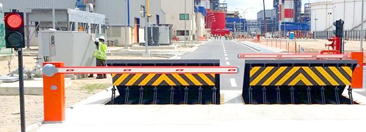
14 and the surface 12 to which the barrier 10 is secured may be made from concrete - Wedge Barriers. 2, the barrier 10 is mounted to or includes an anchor or subframe (e. g., support 30 received FIG. 2 )protected beneath the surface area 12. The bather 10 may be bolted to the anchor or safeguarded to the support by other mechanical bolts. In the illustrated embodiment, the obstacle 10 consists of a wedge plate 16, that includes a portion that is significantly identical with the surface area 12 when the barrier 10 is in the withdrawed setting. To put it simply, vehicles or individuals might overlook the barrier 10 when the obstacle 10 is in the pulled back setting and experience small elevation about the surface area 12 while on the barrier 10. As reviewed thoroughly below, when the obstacle 10 is in the released setting, the wedge plate 16 is held and sustained in an elevated setting by a lifting device of the obstacle 10. In addition, the elements 18 might be bolted or otherwise mechanically paired to each other. In this way, repair work or substitute of several elements 18 may be streamlined and structured. That is, fixing or replacement of single components
18 might be done quicker, easily, and expense efficiently. FIG. In certain personifications, the support 30 may be a steel framework including plates, beams(e. g., I-beams ), and/or other frameworks that are protected within the structure 14, which might be concrete. At the surface 12, a top side 28 of the anchor 30 might go to least partly exposed
, consequently making it possible for the accessory of the obstacle 10 to the anchor 30. g., threaded holes)in several beam of lights or plates of the support 30 may be subjected to the surface 12. In this way, screws 32 or various other mechanical bolts may be made use of to secure the barrier 10 to the anchor 30. As the barrier 10 is installed to the surface area 12 of the structure 14, collection of debris and various other material below the obstacle may be minimized, and elements of the bather 10 may not be revealed to below grade atmospheres. As suggested by recommendation character 52, the training mechanism 50 includes elements disposed below the wedge plate 16. For instance, the components 52 underneath the wedge plate 16 might include an electromechanical actuator, a web cam, one or even more cam surfaces, and so forth. Furthermore, the lifting system 50 includes a spring assembly 54
The springtime pole 58 is coupled to a camera(e. g., cam 80 shown in FIG. 4) of the lifting mechanism 50. The springs 60 disposed about the springtime rod 58 are More Info held in compression by springtime sustains 62, including a fixed springtime assistance 64. That is, the set spring assistance 64 is dealt with about the structure 14 et cetera of the bather 10.
Getting The Wedge Barriers To Work
g., spring assistance 65 )might be repaired to the end of the spring rod 58 to enable compression of the springtimes 60. As the springs 60 are pressed in between the spring sustains 62, the spring setting up 54 generates a force acting upon the camera coupled to the spring pole 58 in a direction 66. The continuing to be pressure applied to
the cam camera deploy release wedge plate 16 may be provided supplied an electromechanical actuator 84 or other actuator. The springtime setting up 54 and the actuator 84(e. g., electromechanical actuator)might operate together to equate the web cam and lift the wedge plate 16.
As mentioned above, the spring assembly 54 exerts a constant force on the webcam, while the electromechanical actuator may be regulated to apply a variable pressure on the web cam, therefore making it possible for the training and reducing( i. e., releasing and pulling back )of the wedge plate 16. In particular personifications, the constant force used by the springtime setting up 54 may be adjustable. g., electromechanical actuator) is redirected here handicapped. As will certainly be appreciated, the spring assembly 54 may be covered and safeguarded from debris or other components by a cover plate(e. g., cover plate 68 received FIG. 4) that might be considerably flush with the raised surface 38 of the structure 14. As pointed out over, in the deployed setting, the wedge plate 16 serves to obstruct accessibility or traveling past the obstacle 10. The obstacle 10(e. g., the wedge plate 16 )may block pedestrians or lorries from accessing a property or path. As reviewed over, the barrier 10 is connected to the support 30 protected within the structure 14,
front braces 71. Therefore, the link assemblies 72 may pivot and turn to enable the collapse and extension of the affiliation settings up 72 during retraction and release of the bather 10. The link assemblies 72 reason activity of the wedge plate 16 to be restricted. If an automobile is taking a trip towards the deployed wedge plate 16(e. For example, in one condition, the security legs 86 may be prolonged duringmaintenance of the barrier 10. When the security legs 86 are deployed, the safety legs 86 sustain the weight of the wedge plate 16 against the surface area 12. As a result, the training system 50 may be shut down, serviced, gotten rid of, replaced, and so forth. FIG. 5 is partial perspective sight of an embodiment of the surface-mounted wedge-style obstacle 10, showing the webcam 80 and the web cam surface areas 82 of the lifting system 50. Especially, 2 webcam surface areas 82, which are described as lower web cam surfaces 83, are placed below the webcam 80. The lower web cam surface areas 83 may be fixed to the surface 12 (e. For instance, the reduced webcam surface areas 83 and the placing plate 85 might develop a single item that is safeguarded to the anchor 30 by bolts or other mechanical bolts. Additionally, 2 webcam surfaces 82, which are Read Full Article referred to as top cam surface areas 87, are positioned over the camera 80 and coupled to (e. In other embodiments, intervening layers or plates may be positioned between the surface 12 and the lower web cam surfaces 83 and/or the wedge plate 16 and the upper web cam surface areas 87 As pointed out above, the webcam
80 converts along the webcam surfaces 82 when the wedge plate 16 is lifted from the retracted placement to the released placement. In addition, as mentioned above, the springtime assembly 54 (see FIG. 3 )might supply a pressure acting on the webcam 80 in the instructions 102 via spring pole 58, which might reduce the pressure the electromechanical actuator 84 is required to put on the camera 80 in order to actuate and raise the wedge plate 16. 1 )to the released setting(see FIG. 4). As revealed, the webcam 80 consists of track wheels 104(e. g., rollers), which call and convert along the webcam surfaces 82 during procedure.